Shopping Cart
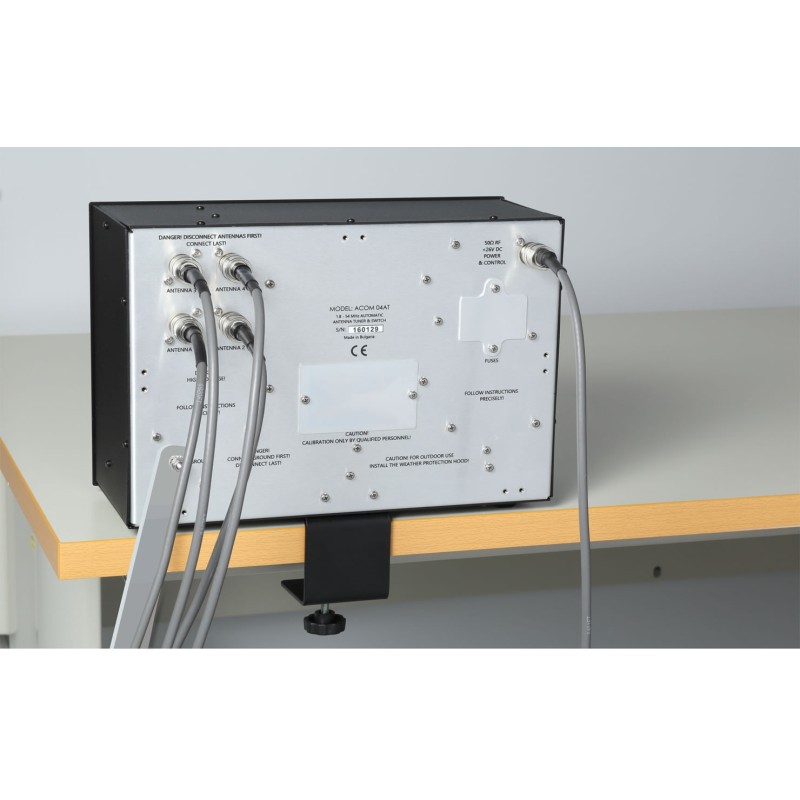

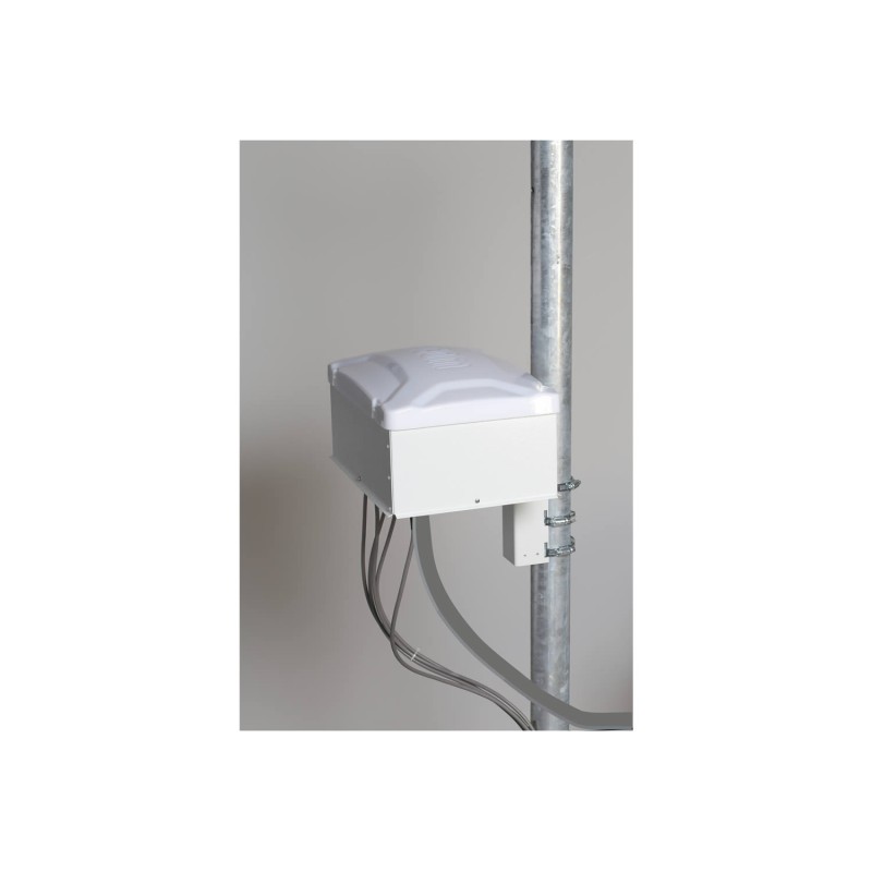


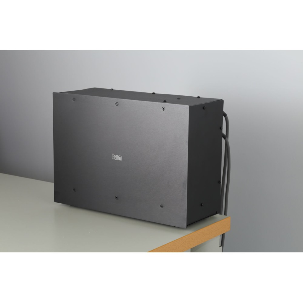
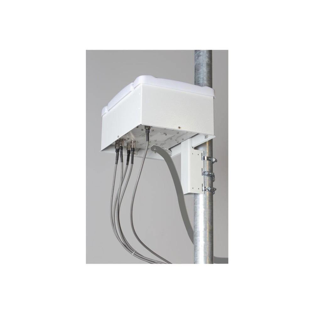
Remote antenna tuner - less losses in the feed line. Designed for installation in a shed, under a shed or open (see mounting kit options). It can be spaced up to 100 m (330 ft) from the amplifier.
Powered and controlled directly from the HF+6m solid state ACF amplifiers only through the amplifier's RF output cable - there is no need for power or control cables between the shack and the tuner.
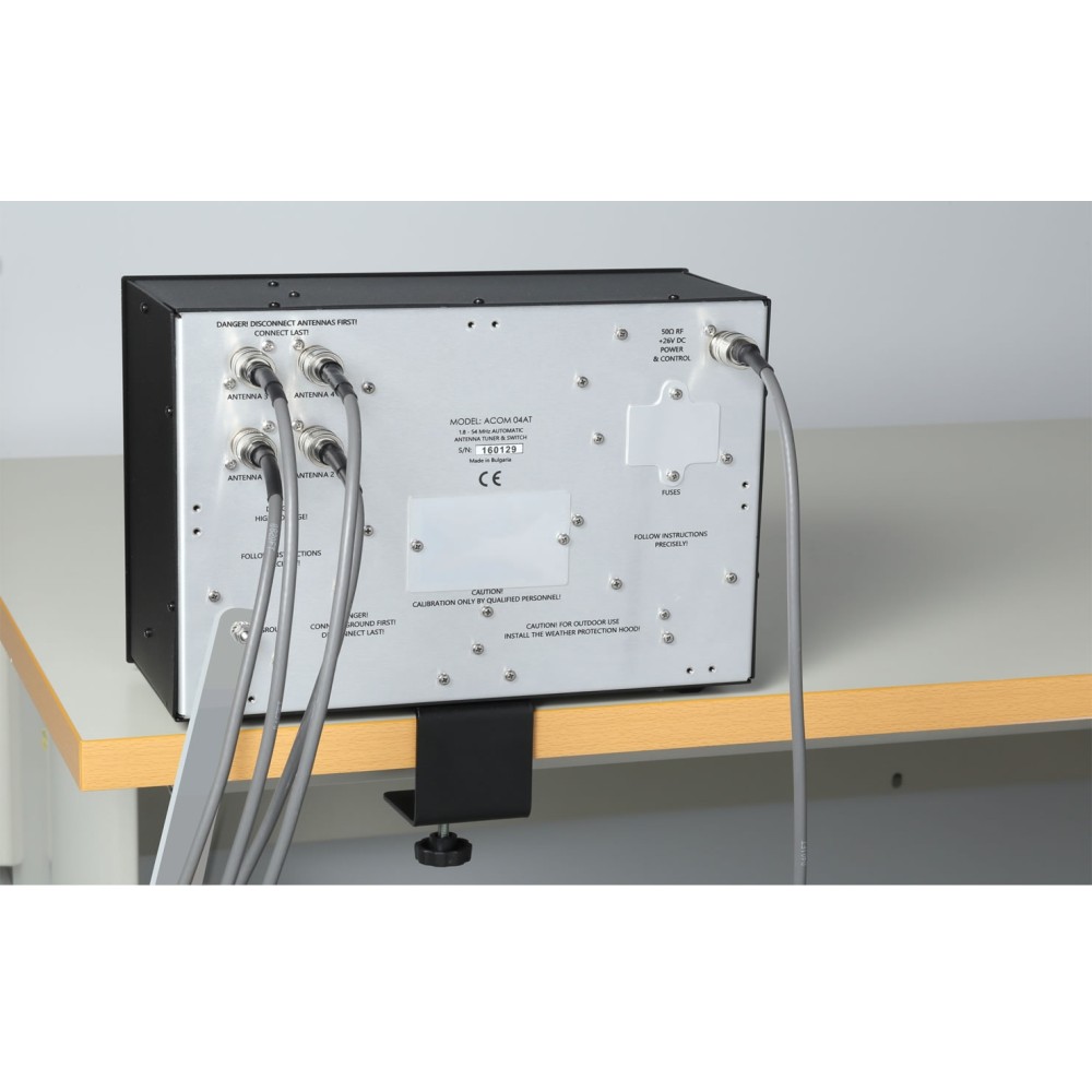
Provides automatic or manual antenna switching and automatic antenna impedance matching to HF+6m solid-state ACF amplifiers, controlled entirely from the amplifier's front panel and CAT transceiver.
Protects the transceiver and amplifier from excessive impedance mismatch during the tuning process.
Works with two types of tuning: full tuning (basic matching cycle) and fast tuning (retrieving user tuning patterns from non-volatile memory.
The complete setup is 100% automated, however a cycle is only started by the operator. User tunings automatically record antenna and frequency changes during amplifier and transceiver operation.
Four typical antenna types: regular, sharp, wide and fixed frequencies are available, so that the operator can adapt the width of the frequency segment to the bandwidth of the specific antenna; BYPASS mode is also available.
Antennas appear with a user-editable number, type, and name on the ACOM Solid State Amplifiers screen.
Tuning availability presented by a graphic scale on the screen of ACOM solid state amplifiers.
There is a lot of information about the antenna and tuner available on the screen of the ACOM solid state amplifier: menu ATU SERVICE, ATU MEASURE, ATU TUNINGS WATCH / DELETE, Resource Estimation Function etc.
You can set the "age" warning to alert you when you try to use an outdated tune.
The user can store all tunings from non-volatile memory into a computer file and load previously stored files into the ACOM 04AT non-volatile memory through the RS232 port of the ACOM solid state amplifier.
Protections: PS voltage, PS reverse polarity, excessive RF voltage, RF current or reflected power on antenna outputs, excessive tuning power, excessive input power, hot switching of relays, overheating etc.
Protected against the formation of static electricity in the antennas by bleed resistors and against nearby lightning by a gas discharge arrester; unused antennas are directly grounded during operation, and all antennas are grounded when ACOM 04AT is turned off.
Frequency coverage: 1.8 to 30 MHz and 50 to 54 MHz, continuously (30 to 50 MHz on request).
Antenna impedance matching ability: all impedances with 50 Ohm-SWR between 1: 1 and 3: 1; (For some higher SWR impedance matches you can also see the power limitations below).
Maximum allowable RF input power, average or continuous (no mode limitations, in brackets - PEP):* (when tuning is possible for SWR above 3:1)
Rem: Operation on SWR above 10:1 is not allowed although matching is possible in some cases.
RF input characteristics:
ACOM-04AT_
98 Items
New
7438641847549
7438641847549
No reviews
Comments (0)
No customer reviews for the moment.
Tap to zoom
